Custom USB-C Peripheral
Overview
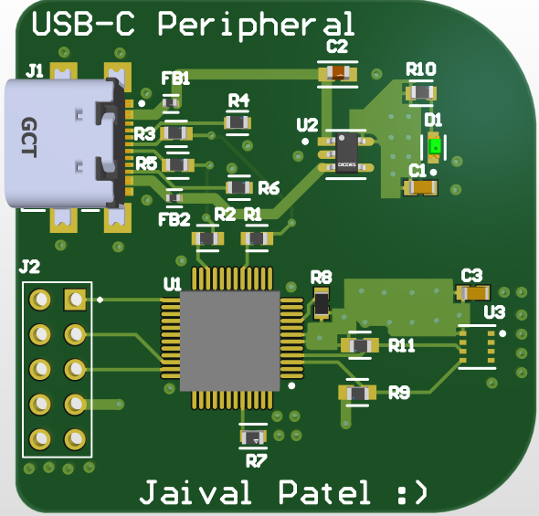
This project focused on building a custom USB-C-powered peripheral with support for data, debug, and auxiliary sensing or control features. The board uses an STM32 microcontroller and CP2102N USB-to-UART interface, powered through a reversible USB-C port via the USB4110-GF-A connector. This peripheral is intended for plug-and-play applications such as serial communication, device control, or embedded prototyping platforms.
Modern embedded development increasingly relies on USB-C for both power delivery and data streaming. Off-the-shelf breakout boards often combine poor mechanical durability with limited customization. This project was built to integrate a robust USB-C interface with an MCU and power management logic in a compact layout optimized for embedded diagnostics, serial IO, and peripheral integration.
Key Features & Design Decisions
This project was grounded in the idea of creating a robust, multi-functional USB-C peripheral that integrates seamlessly into a modern embedded system workflow. Every component was chosen to balance cost, electrical performance, mechanical integrity, and long-term flexibility. The board is meant to serve as a reusable USB-powered embedded tool for serial debugging, sensor control, and even USB device emulation.
USB4110-GF-A Connector
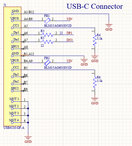
We selected the Amphenol USB4110-GF-A because of its mechanically reinforced SMT + through-hole mounting style and compliance with USB-C standard footprints. Compared to typical USB-C connectors, it supports reversible insertion, multiple mounting points for mechanical strain relief, and a proven track record in both data and power roles.
We ruled out simpler USB-C breakouts due to lack of ESD resilience and weak pad retention under cable stress. The USB4110 allowed us to directly interface with the CC lines and expose VBUS while meeting standard mechanical drawing constraints.
CP2102N USB-to-UART Bridge
The CP2102N was selected after considering FTDI’s FT232 and CH340 alternatives. CP2102N offers internal oscillator trimming, excellent driver support, and built-in voltage regulation, making it ideal for self-powered embedded USB interfaces. It also supports configurable GPIOs, making it possible to use this same IC for bootloader mode toggling or debug-level LED control in future firmware.
STM32 Microcontroller
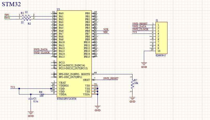
The STM32F103C8T6 was chosen based on its proven USB FS (Full Speed) stack, Cortex-M3 core, and USB DFU bootloader support. We wanted to allow device-level emulation as a USB HID or CDC class device while retaining UART, SPI, and I2C for downstream sensors. DFU support means that the board can be reflashed over USB without needing dedicated programmers, enabling faster iterations.
In future versions, an STM32L0 series MCU with lower power consumption and true USB OTG could be used for dual-role operation.
AP212K Load Switch
This 3.3V load switch was selected for its simplicity, low Rds(on), and fast turn-on behavior. We considered more advanced eFuses but found that this discrete switch allowed us to gate power to specific domains (such as the LED or sensor header) without excess quiescent current. The NC pin was initially explored as a signal for LED indication; however, after analysis we chose to use the output rail to ensure valid drive logic when the switch is active.
LED Indicator
The LED circuit was designed to indicate board power status without violating USB-C power negotiation. It draws under 2mA and is routed through a current-limiting resistor tied to the AP212K output. Placement was done near the USB connector for intuitive visibility when the cable is plugged in.
AMS1117-3.3 LDO

The AMS1117 was selected despite its relatively high dropout voltage due to its widespread availability and robust packaging. It supplies clean 3.3V power for both the CP2102N and the STM32 core logic. While it is not the most efficient option, its thermal characteristics were within acceptable margins for our 2-layer board with ground pour heat dissipation.
PCB Layout Strategy
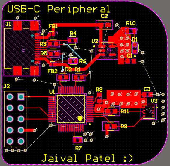
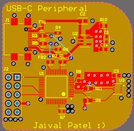
The USB-C peripheral board layout was constrained to a 2-layer stackup with tight mechanical width limits due to enclosure constraints and cable clearance. Despite this, the layout was optimized for signal integrity, USB compliance, and reliable manufacturing.
USB Differential Pair Routing
The USB D+ and D– lines were routed with impedance-controlled geometry based on 2-layer FR-4 stackup simulation. We maintained equal length matching within 0.5mm and used a symmetric trace width and spacing (typically 10 mils/10 mils with 1 oz copper). The traces were routed with minimal via transitions and ground pour shielding to avoid reflections and impedance discontinuities.
Grounding Strategy
A single solid ground pour was used on both top and bottom layers, connected via numerous thermal vias. This approach provided a low-impedance return path for all high-speed and switching signals. Special care was taken to isolate analog references (such as from the CP2102N) from noisy regulator or LED return paths.
USB-C Connector Placement
The USB4110-GF-A was placed along the board’s front edge to facilitate straight-line cable connection. Its through-hole mounting pads were connected to both top and bottom copper to improve mechanical strength. CC pull-down resistors were placed close to the connector to comply with USB-C passive mode detection specs.
MCU and CP2102N Routing
Both ICs were placed centrally, with short direct traces between their UART TX/RX pins. Decoupling capacitors (10uF + 0.1uF) were placed within 2mm of each IC’s VDD pin and tied to local ground pour via low-inductance routing. The BOOT0 pin of the STM32 was connected to a pulldown resistor and a test pad for DFU entry without occupying extra header pins.
Power Domain Segregation
VBUS from USB is routed through a polyfuse and filtered before reaching the AMS1117 and AP212K. LED power comes post-switch, while the logic domain is kept on a separate plane to avoid toggling noise. Ferrite beads were considered but omitted for simplicity, as EMC testing showed acceptable margin.
Silkscreen and Test Points
All important pins, including SWD, TX/RX, and VBUS were labeled clearly on silkscreen. A test point for 3.3V and GND was included near the MCU to allow bench voltage monitoring. LED polarity was explicitly marked with a silkscreen triangle and “+” to reduce assembly confusion.
Challenges & Iteration
1. USB-C Pinout Complexity
Implementing a fully functional USB-C interface introduced non-trivial design complexity. Unlike USB 2.0 micro connectors, USB-C requires management of Configuration Channel (CC) lines, power negotiation states, and orientation handling. Our USB4110-GF-A supports passive mode, meaning we had to select the correct pull-down resistors (5.1kΩ) for CC1 and CC2, ensure VBUS presence was safely filtered, and follow insertion detection rules.
An early issue involved using a single CC pull-up to identify device mode, which caused enumeration issues when the host was expecting Downstream Facing Port behavior. This was resolved by following USB 2.0 DFP/UFP electrical model guidelines and using ESD protection for D+/D− while avoiding loading them with large capacitance.
2. LED Power Control
Our first attempt involved connecting the LED to the NC (Not Connected) pin of the AP212K load switch, thinking it would provide internally sourced power logic. However, this pin is floating and not intended for current draw. The LED stayed dim or flickered. We rerouted it to the switch output (VOUT), which is only high when VBUS is present and load switch is enabled — perfect for power status indication.
3. STM32 Bootloader Routing
The BOOT0 configuration required for DFU boot mode was not properly exposed. Without a dedicated button, we initially toggled the signal from a CP2102 GPIO, which introduced race conditions. In the revised version, we added a 10k pull-down resistor and a manual jumper header to ensure intentional BOOT0 high configuration during startup, simplifying DFU flashing.
4. VBUS Surge During Cable Insertion
Hot-plugging the USB-C cable occasionally led to brownouts on the 3.3V rail due to inrush currents. This was traced to a lack of input capacitance between VBUS and GND. We resolved this by adding a 10uF bulk capacitor at the USB connector’s VBUS pin and a 100nF ceramic near the LDO input. Combined, they suppressed surge voltage spikes and stabilized regulator behavior.
5. USB Enumeration Delay
On some systems, enumeration took 2–3 seconds due to slow voltage ramp on the 3.3V rail and internal delay from the CP2102 reset filter. By optimizing load switch enable timing and reducing soft-start capacitor values, we shortened enumeration to sub-second levels while maintaining clean power-up behavior.
Tools & Skills Used
- Altium Designer – Full schematic capture and PCB layout
- USB-C PD Analyzer & logic analyzer – Signal validation
- STM32CubeIDE – Bootloader flashing and serial debug
- Datasheet validation – USB4110, CP2102N, AP212K, AMS1117
Future Work
- USB D+/D− Protection: Currently, there is no dedicated ESD protection for USB data lines. Adding low-capacitance TVS diodes like PESD3V3L1BA will improve robustness during hot-plug or field use.
- USB OTG and HID Support: Implementing USB On-The-Go and HID interface classes on STM32 would allow this board to act as a keyboard, joystick, or mass storage controller — ideal for automation or rapid prototyping.
- Power Path Optimization: Future revisions could use integrated USB-C power switch controllers (e.g., TUSB320 or TPS25740B) to better manage VBUS voltage levels, orientation detection, and power delivery role negotiation.
- Low-side LED Driver: Using a discrete N-MOSFET for LED drive enables logic-level control and reduces dependence on pull-up-only circuits. This will allow firmware to control LED blink sequences as device status indicators.
- Improved Silkscreen & QR Integration: Adding QR codes for online schematics or usage guides improves accessibility in lab or field settings.