Smart Grid Node with Remote Fault Detection
Overview
The Smart Grid Node is a custom-designed embedded system for real-time voltage and current monitoring, fault detection, and remote telemetry in decentralized electrical infrastructure. Built around the STM32F103C8T6 microcontroller, the node features precision analog sensing, GPS-synchronized real-time clock logging, isolated CAN communication, and power regulation for distributed deployments. It enables scalable fault diagnosis and telemetry across smart grid environments with robust sensor interfaces and data logging capabilities.
Key Features
Voltage & Current Sensing
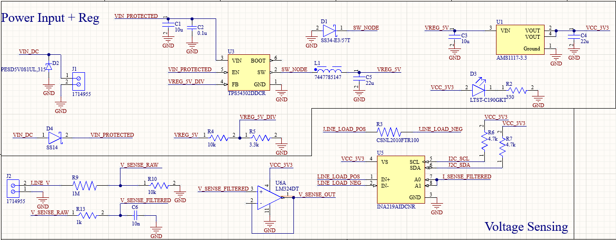
The system monitors critical AC/DC grid lines using precision resistor dividers and current sense amplifiers. Voltage levels are scaled down via high-impedance dividers and filtered with RC stages before reaching the ADC. For current measurement, a shunt resistor feeds into an INA219 current sensor, selected for its I2C interface, built-in ADC, and 0.1% precision current measurement capability.
RTC-GPS Synchronization
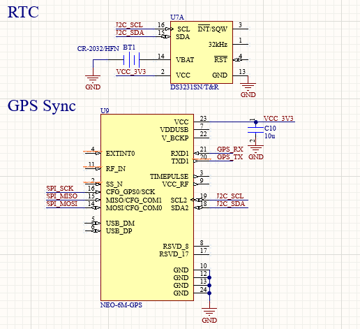
A DS3231 real-time clock logs time-stamped events onto a microSD card. To ensure sub-second global accuracy, a GPS module's 1PPS signal is fed into the RTC or MCU to periodically resynchronize timestamps, a key requirement for grid-wide fault correlation and timing diagnostics.
ESP32 BLE Communication Interface
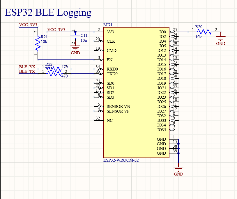
To modernize telemetry and remote diagnostics, the Smart Grid Node integrates the ESP32-WROOM-32E module as its primary wireless interface. This module provides robust Bluetooth Low Energy (BLE) communication, chosen for its:
- Low-power, always-on operation suitable for embedded grid applications
- Integrated dual-core MCU with enough headroom to offload basic protocol handling
- Seamless compatibility with mobile diagnostics tools and field maintenance devices
BLE was preferred over traditional CAN due to:
- Wireless convenience during rapid diagnostics in field deployments without requiring wired access
- Built-in TCP/IP and UART bridge support for future firmware upgrades and API integration
- Support for mesh networking if the grid expands into multi-node monitoring configurations
The ESP32 was connected directly to the STM32 via UART and optionally via SPI for high-throughput streaming. A UART bridge protocol was implemented using DMA on the STM32 side to reduce CPU overhead and allow bidirectional messaging with minimal latency.
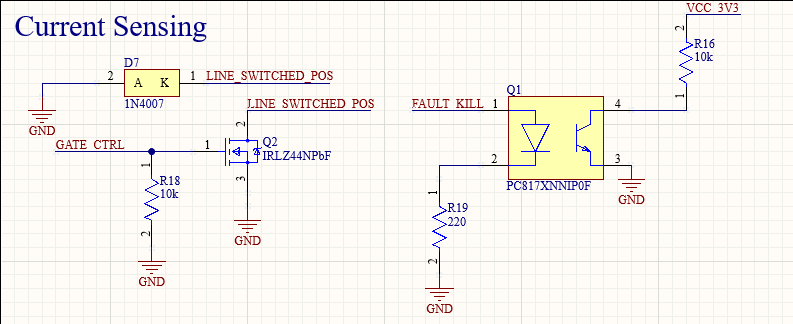
Isolation and Safety
To protect the ESP32 from transients and ESD events common in power electronics environments:
- TVS diodes were placed on TX/RX lines
- The VCC_3V3 rail supplying the ESP32 is isolated via ferrite beads and local bypass capacitors (100nF + 10μF)
- Decoupling strategy was adopted to suppress noise during RF transmission bursts
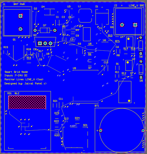
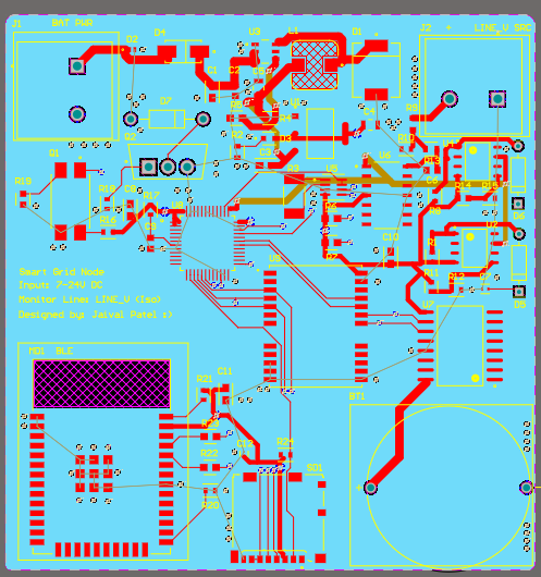
Antenna & Layout
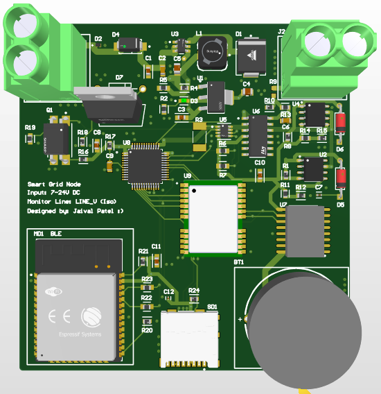
Special care was taken in PCB layout (see Figure 8):
- The onboard antenna was kept free from copper pours and other noisy digital traces
- A cutout in the ground plane underneath the antenna ensured maximum transmission range
- The ESP32 module was placed near the board edge to optimize BLE signal strength in sealed enclosures
Advantages
- Enabled wireless configuration and real-time status broadcasting
- Provided failover telemetry in case of SD card failure or GPS desynchronization
- Supported OTA firmware updates, reducing maintenance overhead
Power Regulation
As seen in Figure 1, the board accepts unregulated 12VDC input and regulates to 5V and 3.3V via AMS1117 LDOs. To prevent overcurrent faults, each rail is protected with resettable polyfuses. Strategic ferrite beads isolate analog and digital domains, minimizing coupling noise from high-frequency switching or telemetry bursts.
Data Logging System
A microSD slot stores sampled data with timestamps for offline analysis. Logging is triggered during predefined voltage/current anomalies or by manual command via CAN. The SD card operates over SPI and is interfaced using a dedicated chip-select to avoid contention during CAN activity.
PCB Layout Strategy
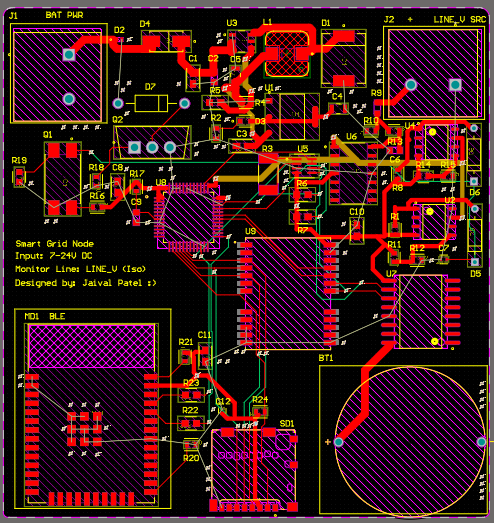
The 6-layer PCB follows a structure of Power + Signal, Power1, Power2 (VCC_3V3 pour), Signal1, Signal2 (unused), and GND. Analog sensing lines are shielded with ground pours and routed away from CAN and MCU switching traces. Clock and reset lines are short, terminated, and isolated from high-current planes. A star-grounding approach ensures low return-path impedance, and decoupling capacitors are placed within 2mm of each IC.
Challenges & Future Work
- Managing ground bounce from large inrush currents during voltage transients
- Thermal drift in voltage dividers, requiring future calibration via onboard EEPROM
- Improving RTC-GPS integration by using interrupt-driven 1PPS syncing
- Enhancing remote reconfigurability via CAN message parsing and bootloader updates
Tools & Skills Used
- Altium Designer – Multilayer PCB layout and signal integrity planning
- STM32CubeIDE – Firmware for ADC sampling, CAN telemetry, RTC-GPS logic
- MATLAB – Sensor signal analysis and trend visualization
- Oscilloscope + Logic Analyzer – Fault injection and timing debug
Transformer-Based Fault Detection for Smart Grid Node
This project implements a self-supervised Transformer-based neural network for real-time fault detection on a custom Smart Grid Node PCB. The system performs embedded anomaly recognition from raw voltage and current waveforms, enabling low-latency fault detection without external supervision or cloud inference.
Both the paper and model repo can be found in the links above.
System Overview
- Microcontroller: STM32F103C8T6
- Telemetry: BLE (ESP32-WROOM-32E)
- Logging: microSD with RTC-GPS synchronization
- Inputs: 1 kHz voltage and current signals across multiple grid lines
- Outputs: Anomaly flags, BLE transmission, local fault logs
Model Architecture
The model uses a Transformer encoder with 3 layers, 4 attention heads, and sinusoidal positional encodings. Trained exclusively on normal signals, the model learns to forecast future signal trajectories using next-step prediction. Faults are detected via elevated reconstruction error — measured as the deviation between predicted and observed voltages and currents.
Self-Supervised Training Pipeline
A custom dataset of synthetic 1-second waveforms (1 kHz sampling) was generated, containing normal and fault conditions such as overvoltage, undervoltage, disconnect, flicker, and drift. Only normal data was used during training. A frozen standard scaler was applied for normalization, and dynamic thresholding was used during inference.
Deployment
The model was quantized and converted to .tflite format. Inference was deployed on the STM32 microcontroller using TensorFlow Lite Micro, with rolling 1-second input windows. Faults were detected every 100 ms based on anomaly score thresholds and transmitted over BLE for immediate response.
Evaluation & Results
- ROC-AUC: > 0.90 across all fault types
- Latency: ~95 ms per inference cycle
- Model Size: 54 KB post-quantization
- Power: ~70 mW average during inference
- Interpretability: Attention maps localize fault onset; PCA visualizations separate latent fault clusters
This approach enables interpretable, real-time fault detection directly on edge microcontrollers, without fault labels or cloud processing. Unlike threshold-based or supervised models, the self-supervised Transformer generalizes to unseen disruptions, offers visual insight into fault timing via attention heads, and operates entirely within the constraints of embedded hardware. This makes it a robust and scalable solution for intelligent grid diagnostics in future decentralized power networks.