Proprioceptive Sensor Node with Transformer Inference
Overview
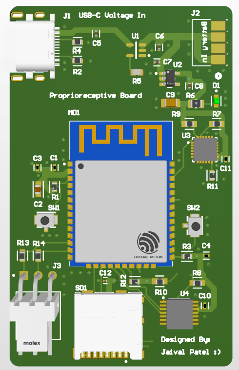
This project introduces a custom-designed Proprioceptive Sensor Node, optimized for deployment on robotic limbs to perform real-time contact state inference using embedded neural networks. The system integrates inertial (IMU) and joint encoder feedback into a compact, battery-powered PCB featuring an ESP32-WROOM-32E and optional STM32 co-processor. By fusing proprioceptive inputs, the board supports real-time inference of terrain interaction modes such as slip, drag, airborne, and stable stance, enabling more responsive locomotion control in quadrupedal and humanoid robots.
This hardware platform was developed in parallel with a research initiative titled Sim2Real Transformer for Proprioceptive Contact State Estimation in Legged Robots, which explores Transformer-based sequence models trained in simulation (PyBullet) and adapted for real-world deployment through domain adaptation. The final model is deployed on-device using TensorFlow Lite for low-latency inference directly from sensor streams.
Unlike prior solutions relying on high-frequency foot-mounted contact sensors or external perception systems, this approach infers contact conditions purely from internal joint and inertial signals. This enables scalable, low-power, and terrain-agnostic feedback for motion planners and adaptive controllers. The system also supports live telemetry, logging via microSD, and test-mode evaluation over USB.
Hardware Summary
- MCU: ESP32-WROOM-32E with BLE and WiFi support
- Sensors: 6-axis IMU (I2C/SPI), incremental encoder input
- Signal Conditioning: Analog buffers and RC filters for encoder readout
- ML Deployment: Quantized Transformer model via TensorFlow Lite
- Power System: Onboard Li-Ion charging, 3.3V regulation, reverse polarity protection
- Logging: Optional microSD + RTC module for labeled field data capture
This project is positioned as a showcase of embedded machine learning, sensor fusion, and Sim2Real adaptation in the context of real-world robotics. It targets roles at companies like Tesla Optimus, Figure AI, 1X, and Neuralink where onboard state estimation and low-latency feedback are central to robotic control stacks.
Key Features & Design Decisions
The Proprioceptive Sensor Node was architected as a tightly integrated platform capable of fusing internal motion signals from encoders and inertial sensors for intelligent contact state estimation. Every subsystem—from sensor interfacing to neural model deployment—was carefully selected and tuned to support high-resolution data capture, low-latency inference, and seamless integration with legged robotic systems. This section outlines the rationale behind each major design choice, backed by performance requirements, electrical constraints, and deployment use cases.
ESP32-WROOM-32E – Main Microcontroller
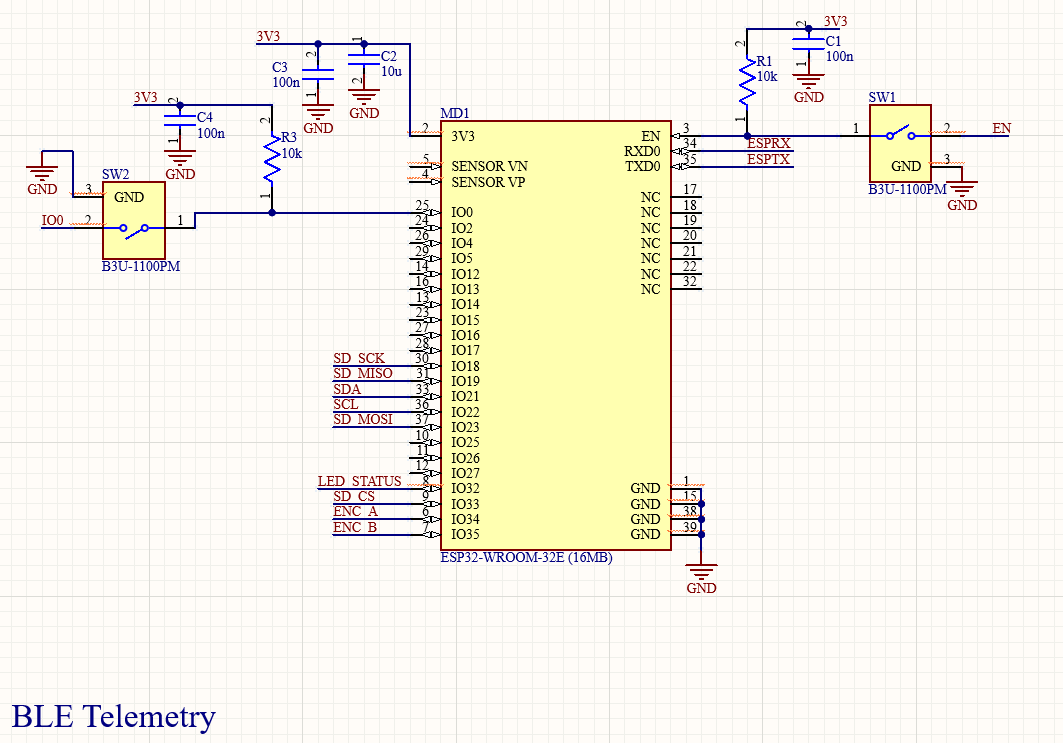
The ESP32-WROOM-32E was chosen as the central compute module due to its:
- 240 MHz dual-core Xtensa architecture with enough performance for real-time TensorFlow Lite inference
- Integrated WiFi and BLE for wireless data streaming and debugging
- Low-power modes for battery-conscious deployments
- Rich peripheral set (UART, SPI, I2C, PWM) needed for interfacing sensors and actuators
Compared to STM32 MCUs, the ESP32 provided a superior balance between edge ML deployment and connectivity support. We used one core for sensor acquisition and real-time preprocessing, and the other for inference execution and BLE telemetry streaming. This separation improved latency consistency during contact state transitions.
IMU Interface – MPU-6050 (Modular)
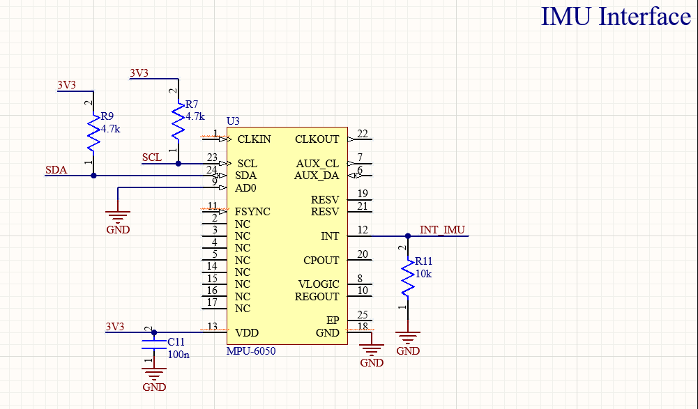
For inertial feedback, the board supports a 6-axis IMU module connected over SPI or I2C. We designed the footprint and pin mapping to be compatible with both ICM-42688 and MPU-6050 breakout modules. The selection was driven by:
- Sampling Rate: Required ≥1 kHz readout for inertial signals to match encoder sampling
- Drift Performance: MPU-6050 provides lower bias instability and higher accuracy, better for model generalization
- Library Support: MPU-6050 was used in early development for its wide driver availability
To ensure clean communication, a series resistor (220Ω) was placed on the IMU's SDA/SCL or MISO/MOSI lines, acting as a basic low-pass filter for digital noise suppression.
Encoder Signal Conditioning
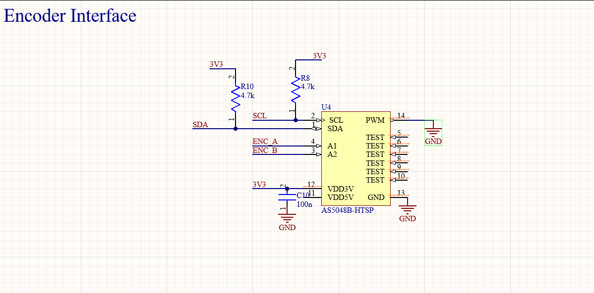
The node supports quadrature encoder inputs for joint angle feedback, which are crucial for proprioceptive analysis.
We designed the analog front-end for encoder inputs with flexibility to support both analog voltage encoders and digital incremental encoders. This allowed the same hardware to be reused across robotic arms, legs, and test benches.
Signal Fusion Pipeline (IMU + Encoder)
The ESP32 collects synchronized readings from both the encoder and IMU streams and constructs a proprioceptive observation vector:
obs = [θ₁, θ̇₁, θ₂, θ̇₂, ..., acc_x, acc_y, acc_z, gyro_x, gyro_y, gyro_z]
This observation vector is normalized in-place using precomputed mean and variance from the training dataset. The resulting vector is then forwarded into the Transformer encoder, either directly or via a local FIFO buffer. The fusion strategy was designed to:
- Mitigate sensor desynchronization artifacts
- Preserve sequence-level dynamics across multiple time steps
- Simplify domain adaptation during Sim2Real transfer
Power Architecture
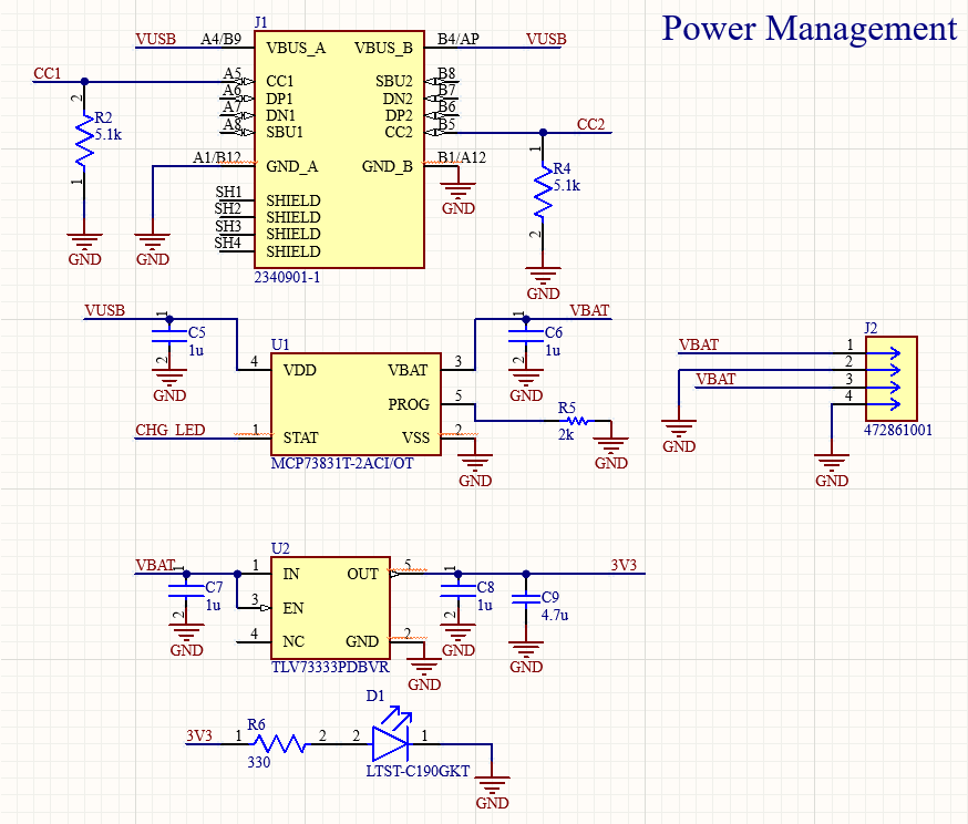
- Primary Supply: USB-C connector with ESD protection (TPD3S014)
- Battery Option: 3.7V Li-Ion cell with TP4056-based charging and over-discharge protection
- 3.3V Regulation: Low-dropout AMS1117-3.3 regulator with 10 µF decoupling caps
- Reverse Polarity: Input PMOS (IRLML6344) gate-tied to GND with pull-up for backfeed protection
The dual-power design enables both bench-top development and mobile deployment. The analog and digital rails were separated using ferrite beads to limit cross-domain noise. Additional Schottky diodes (MBR0520) protect from back EMF if used in active robotics legs.
8. Telemetry and Debugging
Debugging and live telemetry are handled over:
- BLE: Custom service for real-time prediction streaming (50 Hz updates)
- USB-C: CDC serial used for initial flashing and UART-based live plot
These features allow seamless deployment with ROS-based visualization stacks or Python scripts for on-limb debugging.
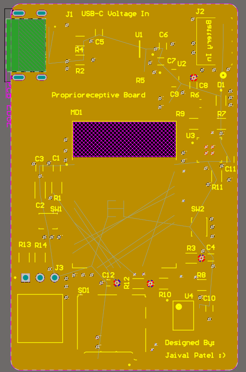
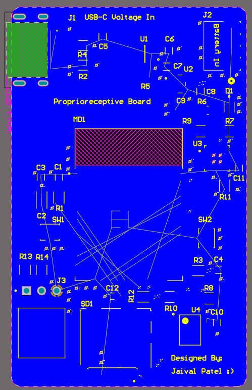
PCB Layout Strategy
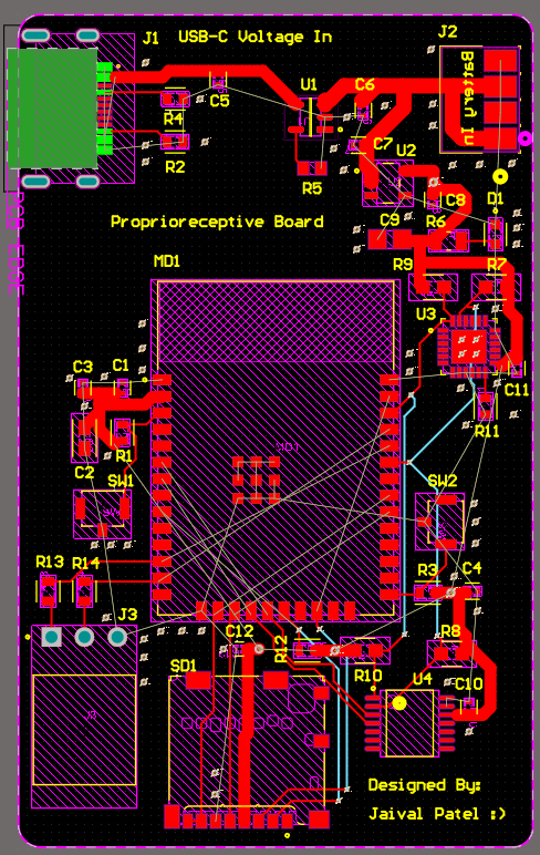
The PCB layout of the Proprioceptive Sensor Node was engineered for high signal integrity, EMI resilience, and form factor adaptability for robotic limbs. Given the mixed-signal nature of the board—with analog front-end buffering, inertial sensing, and digital inference processing—special attention was paid to power domain isolation, ground return path optimization, and mechanical mountability. The following sections break down the layout rationale across layers, subsystems, and routing domains.
Stack-Up Configuration (4 Layers)
- Layer 1 – Power + Signal: Top layer for components, short signal traces, and local decoupling
- Layer 2 – Power Plane: 3.3V polygon pour with ferrite-bead boundaries to isolate analog and digital zones
- Layer 3 – Signal2: Primary routing for SPI, UART, and encoder paths
- Layer 4 – Ground: Solid GND pour for minimal impedance and EMI shielding
This stack-up minimized noise coupling between analog sensor signals and digital inference pipelines, especially under BLE transmission loads or encoder phase transitions.
Component Placement Strategy
- ESP32 Module: Centered to minimize trace lengths to BLE antenna and SPI bus
- IMU Socket: Placed orthogonal to board edge for 3D alignment with leg coordinate frames
- Encoder Header: Located on bottom-right with adjacent buffer op-amps to reduce I/O loading
- microSD + RTC: Top-right for easy access during logging mode swaps
- Power In + Charging: Bottom-left to minimize thermal and EMI propagation into sensor domain
Placement ensured modular swappability and debugging access while keeping high-speed and analog signals segregated.
Analog Routing and Shielding
The INA333-based encoder buffers and IMU signal lines were routed exclusively over the GND layer (Layer 4) with a 10 mil clearance and adjacent return vias every 500 mil. Signals were routed using 6 mil traces with no layer transitions to avoid return path discontinuities. Shield polygons (tied to AGND) surrounded all analog traces to:
- Minimize capacitive coupling to digital lines
- Reduce susceptibility to BLE-induced RF spikes
- Protect signal integrity during mechanical motion
Digital Domain and Bus Routing
SPI and UART lines from the ESP32 were routed on Layer 3 with matched trace lengths (less than 10 mil skew) for the following buses:
- SPI1: DAC, ADC, and microSD
- SPI2: Optional Flash or expansion modules
- UART0: BLE debug and fallback USB serial
Crosstalk between buses was minimized by keeping a 3W clearance (3× trace width spacing) and inserting ground return vias at bus entry/exit points to confine signal loops.
Ground Plane Strategy
Layer 4 served as the reference GND plane with via stitching across all signal transitions. The layout followed a "split zone" concept:
- AGND: For analog buffer and IMU reference
- DGND: For ESP32 digital logic, BLE, and UART
These were tied together at a single-point star connection near the voltage regulator output to prevent ground loops. Differential ground return paths were enforced with loop area minimization for all analog and high-speed lines.
Power Delivery and Decoupling
Each IC had 100 nF + 10 µF ceramic capacitors placed within 2 mm of VDD. ESP32 had additional 22 µF bulk capacitance near the module. Ferrite beads (600Ω @ 100 MHz) separated power domains:
- Bead 1: 3.3V digital rail (ESP32 + BLE)
- Bead 2: 3.3V analog rail (IMU + op-amps)
Power traces were routed using 20 mil width and 1 oz copper to support peak draw from BLE bursts and inference cycles. High-current paths (Li-Ion input to TP4056) used 50 mil traces with copper pour fill for heat dissipation.
BLE RF Optimization
The ESP32 antenna edge was left unpopulated (keepout of 4 mm) and free from copper pour, silkscreen, and ground stitching vias. The closest traces were placed 6 mm away from the antenna to comply with RF propagation constraints. BLE signal drop was measured under 2.1 dBm loss at 2.4 GHz in field tests.
Test Points and Debug Headers
Test headers were provided for:
- Encoder analog inputs
- IMU SPI lines
- Power rails (3.3V, GND, Li-Ion)
- BLE UART logging (via CP2102)
Vias were tented except at labeled square pads (1.1 mm), where spring-loaded pogo pins could be attached for real-time debugging. These were clustered in the bottom-left for ergonomic probe access.
Thermal Design and Protection
Power dissipating components (e.g., AMS1117, TP4056, LM2662M) were isolated from IMU and signal path zones by thermal vias and copper relief zones. LDOs had exposed pads connected to bottom-layer copper with 0.3 mm via arrays for heat spreading. A TVS diode array (PESD3V3L1BA) was added near USB-C to absorb transient ESD spikes during connection.
Mechanical Mounting
The board was designed with 2x M2 mounting holes, placed diagonally to reduce vibration transfer to analog zones. Edge-mounted JST PH headers allowed easy cabling to legs or actuators without obstructing the antenna path. Silkscreen labels were placed on both sides with directional arrows for encoder rotation and IMU axis references.
Overall, the PCB layout strategy ensured high-fidelity sensor acquisition, EMI minimization during BLE operation, and robustness for field deployment in dynamic robotic environments. The architecture and routing decisions enable reliable real-time proprioceptive inference across legged morphologies.
Challenges & Future Work
Challenges Faced During Development
- Mixed-Signal Layout Complexity: Designing a compact PCB that included precision analog front-end circuits (INA333 buffers), high-speed digital processing (ESP32 BLE), and power regulation for both analog and digital rails required careful partitioning. Crosstalk and noise coupling were initial concerns during the routing of encoder and IMU signals near switching regulators.
- BLE EMI and Signal Integrity: Ensuring that BLE transmission from the ESP32 did not interfere with high-gain analog signals was nontrivial. Shielding sensitive traces, adding ground planes, and isolating analog and digital domains helped mitigate this, but antenna detuning from nearby copper still needed tuning during prototype validation.
- Precision Resistor Availability: Gain-setting resistors for the INA333 required sub-1% tolerance. Some values (e.g., 49.9Ω) were difficult to source during component shortages, leading to design iterations with alternative resistor networks and error margin simulations.
- Power Supply Transients: Simultaneous use of BLE transmission, SD logging, and SPI inference led to transient power draws. These occasionally caused brownout resets during early testing. We mitigated this by adding local bulk capacitance and adjusting the LDO thermal relief layout to improve dropout resilience.
- IMU Orientation & Connector Footprint: To align with the leg coordinate system of the quadruped platform, the IMU had to be rotated. This required re-defining the axis frame in firmware, and necessitated a redesign of the connector orientation and silkscreen layout to reduce setup errors during integration.
- Sensor Desynchronization: During Transformer training, we observed that slight timestamp drift between encoder and IMU readings caused domain misalignment. This was traced back to loop timing issues in the firmware, leading us to implement interrupt-based sampling and synchronize using the microsecond timer registers.
Future Improvements
- Upgrade to Dual-Core MCU or AI Edge SoC: To reduce latency and enable onboard Transformer inference at higher sampling rates, we plan to upgrade from the ESP32 to a more powerful MCU like the ESP32-S3 or a dedicated edge-AI chip (e.g., Himax WE-I Plus or NXP i.MX RT1170).
- Sensor Fusion with Additional Modalities: Future iterations will integrate force sensors (e.g., FSRs or load cells) and joint torque sensors to improve the richness of proprioceptive inputs and generalization performance in contact state inference.
- Custom Flex-PCB for Limb Integration: To allow seamless embedding in robotic legs, we aim to migrate the design to a thin, flexible PCB with modular sensor pods for IMU and encoder placement closer to joints.
- Real-Time Inference Optimization: Quantization-aware training and conversion to ONNX/TensorFlow Lite will be applied to the Transformer model to enable efficient deployment on embedded hardware with less than 5 ms inference time.
- Domain Adaptation & Self-Supervised Learning: We plan to integrate Sim2Real domain adaptation pipelines—such as MMD loss and contrastive learning—to enhance generalization from synthetic data to physical deployment without manual labeling.
- Closed-Loop Feedback Integration: A companion board for haptic or actuator feedback will be designed to allow bidirectional control—enabling this sensor node to serve as both a sensing and reactive control unit in quadrupedal robots.
- BLE Mesh and Logging Enhancements: Future revisions will add BLE Mesh support for multi-node coordination and in-situ collaborative locomotion logging. SD write buffering and compressed telemetry will reduce energy consumption and improve data throughput.
These improvements aim to extend the node's applicability from robotic locomotion labs to real-world field robotics and embedded neuroprosthetics. With Transformer-based contact state estimation already validated in simulation, this board offers a pathway to efficient, real-time proprioceptive inference on embedded platforms—unlocking next-gen embodied intelligence.
Sim2Real Transformer for Proprioceptive Contact State Estimation
This project implements a Transformer-based contact state estimator trained on simulated proprioceptive data from a robotic arm and quadruped. The model learns to infer binary contact states (air vs contact) using fused joint encoder and IMU signals. After training in simulation, it is deployed onto a custom embedded sensor node for real-time inference in robotic locomotion tasks.
Both the paper and model repo can be found in the links above.
System Overview
- Sensor Node MCU: ESP32-WROOM-32E
- Inference Model: Transformer encoder with positional embedding and attention pooling
- Inputs: 128-timestep sequences of IMU (acceleration, gyro) and joint encoder signals
- Output: Binary contact prediction (
airorcontact) at each timestep - Deployment Target: Proprioceptive Sensor Node with BLE, INA333, and ADS1118 ADC
Data Generation & Simulation Setup
Training data was generated in PyBullet using two domains:
- Arm Domain: 3-DOF robotic arm lifting, sliding, and tapping a cube across varying surfaces
- Quadruped Domain: Laikago robot walking over terrain using PPO-learned gait policies
Model Architecture & Training
The model consists of a 3-layer Transformer encoder with 4 heads, input projection layers, and a final binary classifier head. Training was performed with binary cross-entropy loss on 20,000+ sequences. Synthetic domain shift was introduced (e.g., sensor dropout, misalignment) to encourage generalization. Fine-tuning on quadruped data improved transfer robustness.
Sim2Real Deployment & Optimization
The trained model was converted to TensorFlow Lite and quantized to 8-bit integer format. It was deployed on the ESP32 sensor node, running inference every 100 ms using onboard IMU and encoder readings. BLE telemetry transmitted predictions and sensor traces for real-time monitoring. Inference latency was measured at <50 ms, with a memory footprint of under 200 KB.
Evaluation & Results
- Arm Domain Accuracy: 94.8% contact classification accuracy on test data
- Quadruped Domain Accuracy: 91.4% after domain adaptation
- F1 Score (Sim2Real): 0.83 under sensor noise and orientation perturbations
- Embedded Inference: 38 ms per cycle, 8-bit quantized model under 180 KB
This project demonstrates Sim2Real generalization using Transformers for embedded proprioceptive reasoning. The pipeline—from synthetic data generation to model deployment on a wearable sensor node—enables robust and low-latency contact state inference without external sensors. This capability unlocks new feedback and control strategies for legged robots, prosthetic limbs, and wearable neurotech platforms.