Avionics Power Management
Overview
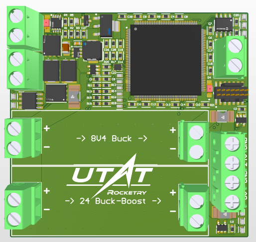
The Avionics Power Management Board was developed as a flight-ready power distribution system for UTAT’s Discovery Rocket. Designed in Altium Designer, the board consolidates battery protection, voltage regulation, and subsystem interfacing in a compact form factor optimized for high-reliability aerospace conditions. The goal was to deliver clean, safe, and well-monitored power to avionics systems operating in harsh, vibration-heavy environments during flight.
Although this was a team project, I was responsible for:
- Designing the battery protection schematic, including reverse polarity protection, current limiting, and transient suppression.
- Laying out the complete PCB in Altium, including regulator placement, connector routing, and heat dissipation strategy.
- Collaborating with firmware and payload teams to determine connector pinouts and voltage tolerances.
PCB Design
Battery Protection Circuit
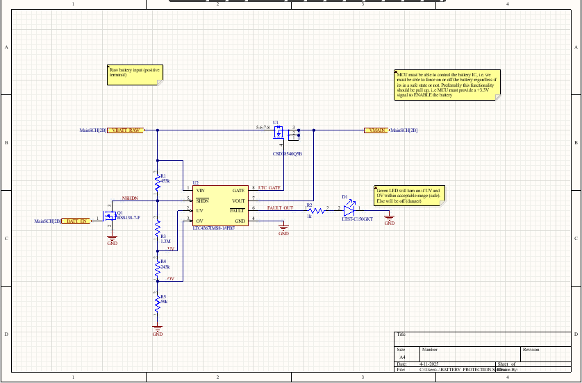
I selected a P-channel MOSFET for reverse polarity protection due to its low Rdson and passive behavior under normal polarity. This design allows the MOSFET to self-block current when polarity is reversed, without any gate driver complexity. A series polyfuse was added to limit sustained overcurrent draw and avoid heating issues in sensitive regulator components.
To suppress inductive spikes during hot-swapping or connector dislodgment, we integrated a TVS diode rated for our maximum voltage margin (~16V). The fuse, MOSFET, and TVS combination forms a reliable first line of defense against power faults.
Voltage Regulation
The board supplies two primary voltage rails — 5V for digital sensors and 3.3V for MCU logic. A buck regulator was chosen over linear for the 5V rail due to thermal and efficiency constraints, especially under full-load conditions (~1.5A).
For analog sections, we used low-noise LDOs to step 5V down to 3.3V with high PSRR, ensuring clean reference signals for IMUs and ADCs. These LDOs were selected for their low dropout and thermal shutdown features.
Connector Strategy
I used JST-GH connectors due to their strong latching, vibration resistance, and standard use across UTAT projects. This reduced the likelihood of mid-flight disconnection and simplified cable harnessing.
Each connector included redundant ground pins and clearly silkscreened labels to avoid field wiring errors. The connectors were oriented toward the board edges to simplify access and prevent crosstalk from tight cable loops
PCB Layout Strategy
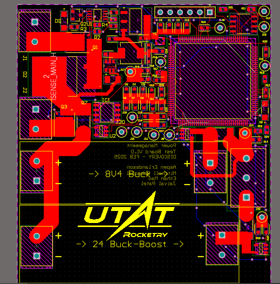
Designed in Altium Designer, the PCB layout was approached with thermal, EMI, and accessibility concerns in mind:
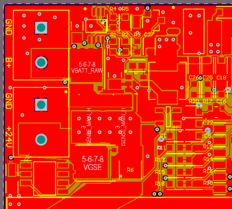
- High-current paths (battery in, regulator out) were routed with wide traces and reinforced with copper pours
- Decoupling capacitors were placed as close as possible to regulator input and output pins, using X7R ceramics for stability
- Star-ground topology was used to separate sensitive analog from high-frequency switching circuits
- Component placement prioritized thermal dissipation from heat-producing ICs, while sensitive analog paths were shielded using strategic ground pours
Challenges & Limitations
- Size Limitations: The board had to fit a defined payload slot, restricting height and width. This influenced part packaging, via placement, and trace routing.
- Power Density: Delivering up to 1.5A on multiple rails within thermal limits required effective heat sinking via ground planes and trace geometry.
Future Work
- Power telemetry: Integrating an INA219 or similar to log current draw per rail during flight
- Fuse re-evaluation: Replace polyfuses with resettable eFuse ICs for better repeatability and precision
- Hot-swap control: Use dedicated hot-swap IC to prevent inrush currents when connecting batteries in the field
- Current foldback: Evaluate current-limiting regulators that include foldback protection to reduce thermal dissipation in sustained fault cases